ASHLAND CITY, Tenn. – Leading water heater manufacturer A. O. Smith has announced the launch of its newest hybrid electric water heater, the Voltex® 50-Gallon Heat Pump, as an extension of the existing Voltex line. As an ENERGY STAR® qualified product, the 50-gallon Voltex is the most energy-efficient heat pump water heater on the market Read more
Water Heaters
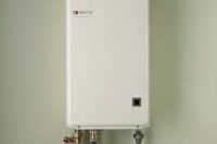
ASHLAND CITY, Tenn. – Leading water heater manufacturer A. O. Smith has announced the launch of its newest hybrid electric water heater, the Voltex® 50-Gallon Heat Pump, as an extension of the existing Voltex line.
As an ENERGY STAR® qualified product, the 50-gallon Voltex is the most energy-efficient heat pump water heater on the market. With an energy factor of 2.75, homeowners can save an average of $350 per year compared with standard electric models. The Voltex is truly user friendly, with an easy to use electronic interface, multiple operating modes to meet homeowner needs and quiet operation.
This new residential product meets plumbing code regulations for three bedroom homes with a 67.5 gallon first-hour delivery. Further benefits include a washable and reusable air filter and a SmartPort connection that allows homeowners to connect with future home management and utility smart grid applications.
“A. O. Smith prides itself on being the leader in the industry,” said A. O. Smith Marketing Director David Chisolm, “and we strive to provide the best technology on the market. Conserving energy and saving money is important to our customers, which makes the 50-gallon Voltex Heat Pump Water Heater a great choice for residential application.”
About A. O. Smith
A. O. Smith Corporation is a leading global manufacturer and marketer of residential and commercial water heaters. A. O. Smith offers its customers an additional competitive advantage in that the company designs, builds, distributes and field supports the world’s broadest and deepest line of residential and commercial water heaters, as well as commercial boilers. This single-source concept simplifies ordering, installation and service and is backed by more than 70 years of research and innovation. For more information, visit www.hotwater.com. For the most up-to-date industry news, like us on Facebook and follow us on Twitter.
KEY WATER HEATING CHARTS AND FORMULAS by Rich Grimes It’s 2012 already and in this issue we will try to give you plenty of information and useful charts related to water heating. I don’t receive many requests so I am glad to accommodate on such a pertinent subject. The best part is that you won’t Read more
KEY WATER HEATING CHARTS AND FORMULAS
by Rich Grimes
It’s 2012 already and in this issue we will try to give you plenty of information and useful charts related to water heating. I don’t receive many requests so I am glad to accommodate on such a pertinent subject. The best part is that you won’t have to read too much from me as these charts and formulas speak for themselves! So here we go…
BTU
A British Thermal Unit (BTU) is a measurement of heat energy. One BTU is the amount of heat energy required to raise one pound of water by 1ºF. Water weighs 8.33 pounds per gallon so we can calculate that one gallon of water requires 8.33 BTU to raise the temperature 1ºF.
BTU CONTENT OF FUELS
ENERGY SOURCE BTU PER HOUR
COAL
1 Pound = 10,000 – 15,000
1 Ton = 25 Million (app.)
ELECTRICITY
1 KW = 3,412
OIL
1 Gallon #1 Fuel = 136,000
1 Gallon #2 Fuel = 138,500
1 Gallon #3 Fuel = 141,000
1 Gallon #5 Fuel = 148,500
1 Gallon #6 Fuel = 152,000
GAS
1 Pound of Butane = 21,300
1 Gallon of Butane = 102,800
1 Cubic Ft. of Butane = 3,280
1 Cubic Ft. of Manufactured Gas = 530
1 Cubic Ft. of Mixed = 850
1 Cubic Ft. of Natural = 1,075
1 Cubic Ft. of Propane = 2,570
1 Pound of Propane = 21,800
1 Gallon of Propane = 91,000
HORSEPOWER
1 Boiler Horsepower (BHP) = 33,475 BTU
1 Boiler Horsepower (BHP) = 34.5 Pounds of Steam @ 212ºF
1 Boiler Horsepower (BHP) = 9.81 KW
COOLING
1 Ton of Cooling = 12,000
GAS INFORMATION
NATURAL PROPANE
Specific Gravity = 0.62 1.52
Flammability Limits (GAS/AIR Mixture) = 4%-14% 2.4%-9.6%
Maximum Flame Propagation (GAS/AIR Mixture) = 10% 5%
Ignition Temperature = 1200ºF 950ºF
1 Pound of Gas (1 PSI) = 28″ Water Column (w.c.)
1 Pound of Gas (1 PSI) = 16 Ounces (oz.)
1 Therm = 100,000 BTU
ELECTRICAL INFORMATION
1 Kilowatt (kW) = 3412 BTU Per Hour
1 Kilowatt (kW) = 1000 Watts Per Hour
1 Kilowatt Hour (kWH) will evaporate 3.5 pounds of water from and at 212ºF
Amperage – Single Phase (1 Ø) = KW x 1000 or WATTAGE
VOLTAGE VOLTAGE
Amperage – Three Phase (3 Ø) = KW x 1000 or WATTAGE
VOLTAGE x 1.732 VOLTAGE x 1.732
WATER HEATING FORMULAS
BTU Per Hour Requirement
BTU OUTPUT = GPM x Temperature Rise x 8.33 Lbs/Gallon x 60 Minutes
BTU INPUT = (GPM x Temperature Rise x 8.33 Lbs/Gallon x 60 Minutes)
% Efficiency
Heat Transfer Efficiency
% EFFICIENCY = (GPH x Temperature Rise x 8.33 Lbs/Gallon)
BTU/Hr INPUT
Heat-Up Time
Time in Hours = (GPH x Temperature Rise x 8.33 Lbs/Gallon)
(BTU/Hr INPUT x % Efficiency)
Temperature Rise
Temp. Rise (∆T) = (BTU/Hr INPUT x % Efficiency)
(GPM x 60 Minutes x 8.33 Lbs/Gallon)
GPH Recovery
Electric = (kW INPUT x 3412 BTU/kW x % Efficiency)
(Temperature Rise x 8.33 Lbs/Gallon)
Gas = (BTU/Hr INPUT x % Efficiency)
(Temperature Rise x 8.33 Lbs/Gallon)
MIXED WATER FORMULA
% of Hot Water Required = (Mixed Water ºF – Cold Water ºF)
(Hot Water ºF – Cold Water ºF)
WATER INFORMATION
1 Gallon = 8.33 Pounds
1 Gallon = 231 Cubic Inches
1 Cubic Ft = 7.48 Gallons
1 Cubic Ft = 62.428 Pounds (at 39.2ºF – maximum density)
1 Cubic Ft = 59.83 Pounds (at 212ºF – boiling point)
1 Ft of Water Column (w.c.) = .4333 PSI
Water expands 4.34% when heated from 40ºF to 212ºF
Water expands 8% when frozen solid
OPEN VESSEL
BOILING POINT @ 0 PSI ALTITUDE
212ºF 0 Feet (Sea Level)
210ºF 1000 Feet
208ºF 2000 Feet
207ºF 3000 Feet
205ºF 4000 Feet
203ºF 5000 Feet
201ºF 6000 Feet
199ºF 7000 Feet
CLOSED VESSEL BOILING POINT @ PSI @ Sea Level
BOILING POINT GAUGE PRESSURE
212ºF 0 PSI
240ºF 10 PSI
259ºF 20 PSI
274ºF 30 PSI
287ºF 40 PSI
298ºF 50 PSI
316ºF 70 PSI
331ºF 90 PSI
ONLINE RESOURCES
There are an unlimited number of online tools and calculators for every mathematical formula. The internet is full of helpful resources to get the job done quicker. Here are a few links to some useful websites:
WEBSITE/PROGRAM WEB ADDRESS
Amtrol Expansion Tank Sizing http://amtrol.com/support/sizing.html
Engineering Toolbox Calculators http://www.engineeringtoolbox.com/
State Water Heater Sizing (Online) http://www.statewaterheatersizing.com/
AO Smith Water Heater Sizing (Online) http://www.hotwatersizing.com/
Lochinvar Water Heater Sizing (Download) http://www.lochinvar.com/sizingguide.aspx
Cylinder Calculator (Storage Tanks) / Other Math Calculators http://www.calculatorfreeonline.com/calculators/geometry-solids/cylinder.php
Electrical/Mechanical/Industrial/Civil/Chemical/Aeronautical Calculators http://www.ifigure.com/engineer/electric/electric.htm
B&G System Syzer (Piping/Pressure Drop Tool Download) http://completewatersystems.com/brand/bell-gossett/selection-sizing-tools/system-syzer/
B&G Selection and Sizing Tools (Pumps, Regulators, Steam and Condensate) http://completewatersystems.com/brand/bell-gossett/selection-sizing-tools/
Taco Pump Selection Wizard (Online Pump Selector) http://www.taco-hvac.com/en/wizard_pumps.html
Lawler Mixing Valve Sizing (Online – account setup) http://www.lawlervalve.com/index.php?p=page&page_id=Sizing_Program
DSIRE Database of State/Federal Renewable Energy Rebates http://www.dsireusa.org/
ASCO Valve Online Product Selector (Valves – solenoid, pilot, pneumatic, etc.) http://www.ascovalve.com/Applications/ProductSearch/ProductSearch.aspx?ascowiz=yes
SUMMARY
There is a lot of other information that we could add such as Steam. It is a viable heating source and there are several factors that must be considered such as operating pressure, steam trap and condensate line sizing and so on. We will have to do a separate article on Steam in a future issue.
The charts and information above are all essential to water heating. They are proven mathematical formulas of algebra and geometry. If you input the accurate information then the results will be correct. It is also good to use the online tools and calculators. They are true time savers.
Thanks and we’ll see you in the next article!
Thermal Expansion by Rich Grimes We have covered several topics related to water heating in previous articles and we will continue with the issue of Thermal Expansion. Thermal Expansion will occur whenever there is a heat source and the piping loop is “Closed”. This implies that the piping is operating as a Closed Loop, separated Read more
Thermal Expansion
by Rich Grimes
We have covered several topics related to water heating in previous articles and we will continue with the issue of Thermal Expansion. Thermal Expansion will occur whenever there is a heat source and the piping loop is “Closed”. This implies that the piping is operating as a Closed Loop, separated from incoming fresh water by a check valve of a backflow device. Closed Loop systems typically operate at lower system pressures than incoming cold water pressures. A closed loop heating boiler is a good example of such a system. The water in the closed loop of piping is not potable and must be prevented from backflow into the domestic cold water supply. Once a backflow device is installed and the loop is heated, thermal expansion will occur and must be controlled. This is also an issue on domestic water heaters installed on “Open Loop” piping because of code required BFP devices.
HISTORY
Hydronic heating boilers have always required an expansion tank and the sizing is calculated to absorb the system’s thermal expansion. Water heaters were traditionally installed with no check valve on the cold water supply, so the cold water piping would absorb the expanding heated water. Larger commercial systems would utilize a swing check valve to prevent over-heating of the cold water supply. Plain steel expansion tanks could not be used on fresh water systems so the common practice was to drill a ¼” hole in the flapper of the check valve to allow expanding hot water to escape into the cold water supply. This sounds crazy but it was documented in various manufacturer’s literature and did help to alleviate the problem. But it did not fix the problem.
But along came Backflow Prevention and it created an immediate need for Domestic Thermal Expansion Control. The basis of BFP is to prevent cross contamination, but the result was a “Closed” piping loop that experienced thermal expansion just like a boiler! This is similar to Newton’s Law because for each and every action there is an equal and opposite reaction. All of a sudden there were expansion issues that did not exist before!
Manufacturers of expansion tanks provided tanks with internal bladders that could be pressurized and separated the steel tank from the fresh water. The same tank design was being used on fresh water well systems.
Today, backflow prevention is a standard installation practice on domestic cold water systems. There are various BFP’s and Thermal Expansion devices that can be used, depending on local code requirements.
PRINCIPLE
Water cannot be compressed like air so it will expand, creating more volume. This expansion creates a pressure increase that can be entrapped by a check valve or BFP. Water will expand at a rate of .000023 percent for each degree of temperature rise. This may not seem like a lot but if a 30 gallon water heater was heated from 60ºF to 140ºF (80ºF Rise) it would increase in volume by .55 gallons. The additional ½ gallon of water must expand as the volume increases. If there is not a means of expansion control then the expanding water will lift the relief valve to discharge the additional volume and increasing pressure. Temperature and Pressure Relief Valves will discharge with a condition of 210ºF or 150 Psi. Expanding water can easily exceed the 150 Psi T&P valve rating when heating up a “closed” water heater. This is commonly seen at the end of the heating cycle when the relief valve lifts for several seconds. It is also commonly misdiagnosed as a bad relief valve and the replacement relief valve functions just like the “defective” valve, discharging water.
Expansion is a predominately a pressure issue, but temperature accelerates the expansion. Thermal Expansion, expansion caused by heating. New water heaters have a clean heating surface and can expose thermal expansion where the old heater did not display such signs. I have also seen where houses with ½” piping experience more expansion issues than houses piped in ¾”. This is due to the same rate of volume increase with less piping to absorb the expansion. Old heaters that are full of scale have an extended, slower heating cycle that helps to gradually add the expansion.
This will also make you realize how much expansion can be created by large commercial systems with high BTU inputs.
THERMAL EXPANSION TANKS
Domestic Thermal Expansion tanks are constructed typically of an epoxy coated steel shell. They have a butyl rubber internal bladder that separates the bare steel from the fresh water. They have a connection for connecting to the cold water supply and an air connection for pre-charging the bladder pressure. The bladder pressure MUST be preset equal to or a little greater than the incoming cold water pressure. This is crucial to installing an expansion tank. A setting of 10 Psi greater than measured cold water pressure is recommended to compensate for varying pressures. For instance, a neighborhood typically has a little less pressure in the morning (heavy use time) than it might at 2:00 PM when the water usage is less. Cold water pressure should be measured with a hose bibb pressure gauge or similar dial-type gauge. Almost every expansion tank comes factory pre-charged to 40 Psi. While 40 Psi may be expected on a well system, pressures of 60 to 80 Psi are common in Florida. A tank that is pre-charged to 40 Psi and is installed on a 60 Psi system will be ineffective. The air in the bladder is pushed all the way up into the tank and it cannot absorb any expansion. An expansion tank must be pre-charged with no water pressure present for the proper setting.
The connection of the expansion tank to the cold water supply is also critical. The expansion tank MUST be installed between the heater and the cold water check valve or BFP. The hot water will try to expand away from the heater towards the cold supply where it is absorbed by the Expansion Tank.
Bladder style expansion tanks can be mounted in the most convenient location and piped over to the system, unlike gravity style tanks which must be located at the highest point of the system. Bladder tanks are also smaller in size to an open gravity tank due to their ability to absorb expansion at a higher volume.
Thermal expansion tanks are sized based on volume of water, incoming water temperature and pressure, stored water temperature and possibly some pressure and expansion factors. There are various sizing programs available in print and online. There are probably ten to twenty manufacturers of domestic thermal expansion tanks to choose from. There are also larger bladder type tanks available for commercial applications.
SUMMARY
Domestic Thermal Expansion Tanks are required in most systems today due to backflow prevention devices. These devices provide a solid, positive shut off that will not allow for any thermal expansion. There are also other means of expansion relief, but most involve a self-seating valve that will lift and allow the relief of the additional volume, prior to the heater T & P valve lifting. The Bladder type tanks provide proper expansion protection and also a little protection from water hammer and thermal shock. Systems that experience extreme hammer or thermal shock should be provided with additional protection such as water hammer arrestors or shock absorbers.
It is important to pre-charge the expansion tank and make sure that the connection to the system is located between the water heater and the check valve/BFP. If a tank is existing and has the incorrect pre-charge air pressure, the cold water pressure must be relieved so the tank air pressure can be properly set. Thermal Expansion tanks will prolong the life of water heaters as they absorb the excess volume created by thermal expansion. Backflow prevention is primary to keeping our water supplies safe from cross connection contamination. This technology has created the need for domestic thermal expansion devices that are here to stay.
Thanks and we’ll see you in the next article!
Sincerely,
Rich Grimes

We are back with another article and this time we will look at water quality and its effect on water heaters and boilers. BOILERS Boilers are typically closed loop systems where fresh water is used to fill the system but the same fluid is used over and over again. After a system fill, very small Read more

We are back with another article and this time we will look at water quality and its effect on water heaters and boilers.
BOILERS
Boilers are typically closed loop systems where fresh water is used to fill the system but the same fluid is used over and over again. After a system fill, very small amounts of fresh water will enter to maintain system pressure. Chemicals are added to inhibit corrosion and prevent freezing. The dissolved oxygen, calcium and other minerals will precipitate or “fall out” of the heating fluid. They only become present if fresh water is allowed to re-enter the closed loop system.
For instance, I experienced a scaled up heat exchanger on a properly installed closed loop boiler. After further inspection of the closed loop fluid it was found to be untreated fresh water. The maintenance crew had been using a boiler drain valve to extract heating hot water for cleaning purposes. This occurred every day where they would fill a 5-gallon bucket twice a day. They had access to a Domestic water heating system (right next to the boiler) that resolved their boiler scaling issue.
WATER HEATERS
Water heaters are designed to heat volumes of fresh water up to temperature for domestic and potable uses. The fresh water can contain various minerals and chemicals that will shorten heater life or cause adverse conditions when heated.
Scale build-up is the single most cause of water heater failure and loss of efficiency. The nature of water heater design can be a definitive factor in longevity and overall efficiency but the water conditions are area, utility or site specific. Calcium is present in water and it wants to stick to heating surfaces as it changes from suspension to solids.
ANODE ROD PROTECTION
Most tank-type water heaters use a ceramic porcelain Glass lining to protect the steel vessel interior from fresh water. The glass lining requires a sacrificial anode to cover and protect any weak spots on the lining. Electrolysis will attack the weakest spot on the lined tank interior and the anode is designed to give itself up to fill that particular spot. Over the life of the heater the anode will sacrifice or “give up” small amounts of its soft metal to protect the lining.
The two metals most commonly used in water heaters for anodes are either Magnesium or Aluminum. These metals are softer than steel and less noble. They can sacrifice themselves prematurely if attacked by the content of the water. These have distinct signs and smells that help to recognize how to deal with such issues.
Here are some common water problems related to water heaters and anode rods:
Hydrogen Sulfide – reaction created by a sulfate-reducing bacteria. It occurs with water that has high sulfur content and it attacks the magnesium anode. It is referred to as “Rotten Egg” smell. Hydrogen Sulfide gas in large quantities can be toxic and explosive.
Hydrogen Sulfide normally can be corrected by changing to an aluminum anode rod after performing a complete chlorination and flush of the tank and piping to kill the bacteria. Some manufacturers specifically use an aluminum anode rod as standard equipment in Florida to avoid the reaction to magnesium.
Aluminum Hydroxide – reaction caused by high pH water. It occurs many times in areas with high chlorine/chloramines in the water supply. Chlorine has a very high pH of 11.7. This reaction forms a jelly-like substance on the anode rod and in the bottom of the tank. It can appear as grey, blue or green beads or gel. The odor produced smells something like week-old trash so it is not something you can tolerate very long!
High pH also means alkaline or scaling so the tank must be flushed out and possibly de-scaled. The reaction is treated with the other viable anode made of magnesium.
Water Softeners – water softeners reduce grains of hardness through a process of ion exchange. Most water softeners exchange sodium (salt) ions with insoluble calcium and magnesium ions. Sodium can increase electrical conductivity and accelerate anode consumption. Use of water softeners warrant monitoring of pH level, conductivity and anode inspection at a regular interval, no less than once a year.
Stagnation – allowing the same water to exist in the tank for long periods of time will result in stagnation. The potential for bacteria increases. This can attack the anode and the results are smelly water and a heater that needs service. Many seasonal residents of Florida will leave their winter homes and forget to drain down their water heater. They typically turn off the power before they leave and the low temperature, stagnated water starts creating the perfect Petri dish. The other application is a larger storage heater that does not get used much, where very little fresh water enters to replenish the stagnated water. A 50 gallon heater on a break room sink is a great example of an over-sized and under-used heater.
Grounding – bad earth grounding can create an electrical potential that will erode the anode at a rapid rate. Once the anode is gone, the steel tank is attacked by the electrolysis.
NEW ANODE TECHNOLOGY
There is newer technology on water heaters for cathodic protection. Electronic controls can help to implement a non-sacrificial anode. The benefits of such a device are a milestone in tank protection.
The Powered Anode is a titanium rod that is immersed in the top of the heater tank. It can function as a Low Water Cut Off to insure that the tank is full of water. Titanium is a very hard metal, mostly impervious to fresh water and much more noble than steel. It will last longer than the water heater and does not sacrifice itself. So there is no smell that will be generated by this non-sacrificial anode rod.
The electronic controller will send out a micro-DC current to the Titanium rod to offset electrolysis. The electronic controller sends out more micro-DC voltage as the tank lining gets older. At some point, the electronic control cannot put out any more current. The integrity of the tank lining is so diminished it is already leaking or within days or weeks of leaking. This is a valuable feature, to know that when you cannot maintain power to the electronic anode rod, you are about to experience a tank failure in the very near future. Time to schedule a change out!
OTHER WATER ISSUES
Water can and will contain a variety of chemicals and minerals that can create adverse conditions when heated. The heating of the water will increase precipitation of scale. It causes the calcium to leave solution form and become a solid that sticks to itself and accumulates on heating surfaces.
High iron content is very common in Florida with well systems. Tannic acids will turn the water yellow to brown in color. Lime is naturally present in every water source to some degree. Bacteria can also be thriving in a particular water supply. The process of heating accelerates the various reactions. There is a wide range of targeted treatment and filtration products that can address these such as UV, Iron filters and the like.
It is important to remember that it is not the fault of the water heater, but a adverse reaction to the water…